


How to Choose the Right KF Fittings
KF fittings — also called NW (Nennweite) or ISO-KF fittings — are the most widely used quick-connect system in laboratory and industrial vacuum. They're fast to assemble, require no tools for basic connections, and are reusable across hundreds of cycles. But choosing the wrong size, clamp type, or seal material is one of the most common reasons a vacuum system fails to reach its target pressure. This guide gives procurement teams and lab technicians a practical framework for getting the selection right the first time.
1. What Is a KF Fitting?
KF (Klein Flange) fittings are a family of standardised vacuum components defined under the ISO 2861 standard. Each fitting has a smooth, flat face with a small recess to locate a centring ring and O-ring. Two mating flanges are held together by a clamp — no bolts, no threading. The O-ring, compressed between the centring ring and both flange faces, creates the vacuum seal.
The system is rated for rough vacuum through to high vacuum (≥ 10⁻⁷ Pa) when properly assembled. It is not suitable for ultra-high vacuum (UHV) — for pressures below 10⁻⁷ Pa, ConFlat (CF) flanges with metal gaskets are required.
|
NOMENCLATURE TIP KF25, NW25, and ISO-KF25 all refer to the same 25 mm nominal bore fitting. "KF" is the German designation (Klein Flange), "NW" stands for Nennweite (nominal width). The numbers refer to the nominal bore in millimetres — not the outer flange diameter, which is larger. |
2. KF Sizes — Choosing the Right Bore
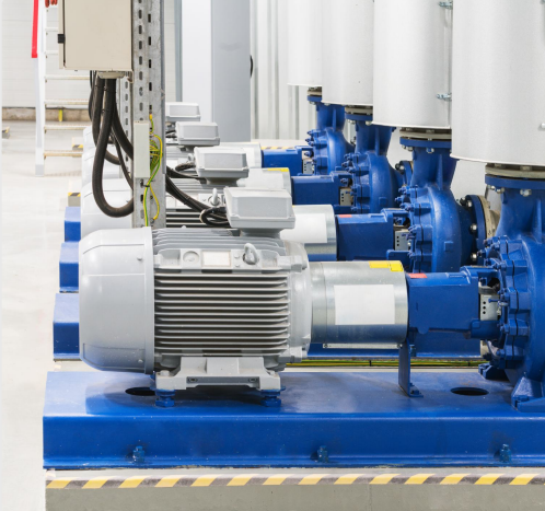
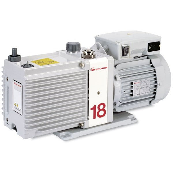
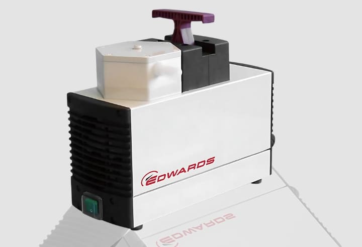
KF fittings are available in five standard sizes: KF10, KF16, KF25, KF40, and KF50. The three most common in laboratory and light industrial vacuum are KF25, KF40, and KF50. Choosing the wrong bore size is often a conductance problem — too small, and gas flow is choked; too large, and the cost and physical footprint increase unnecessarily.
|
Size |
Nominal Bore (mm) |
Outer Flange Ø (mm) |
O-ring ID (mm) |
Typical Application |
|
KF10 |
10 |
21 |
~10 |
Small gauge ports, vent lines |
|
KF16 |
16 |
28 |
~16 |
Gauge heads, small pumps, crossovers |
|
KF25 |
25 |
40 |
~24 |
General lab connections, small turbos |
|
KF40 |
40 |
55 |
~37 |
Main pump connections, larger turbos |
|
KF50 |
50 |
75 |
~47 |
High-throughput backing lines, large rotary pumps |
Matching Size to Pump Inlet
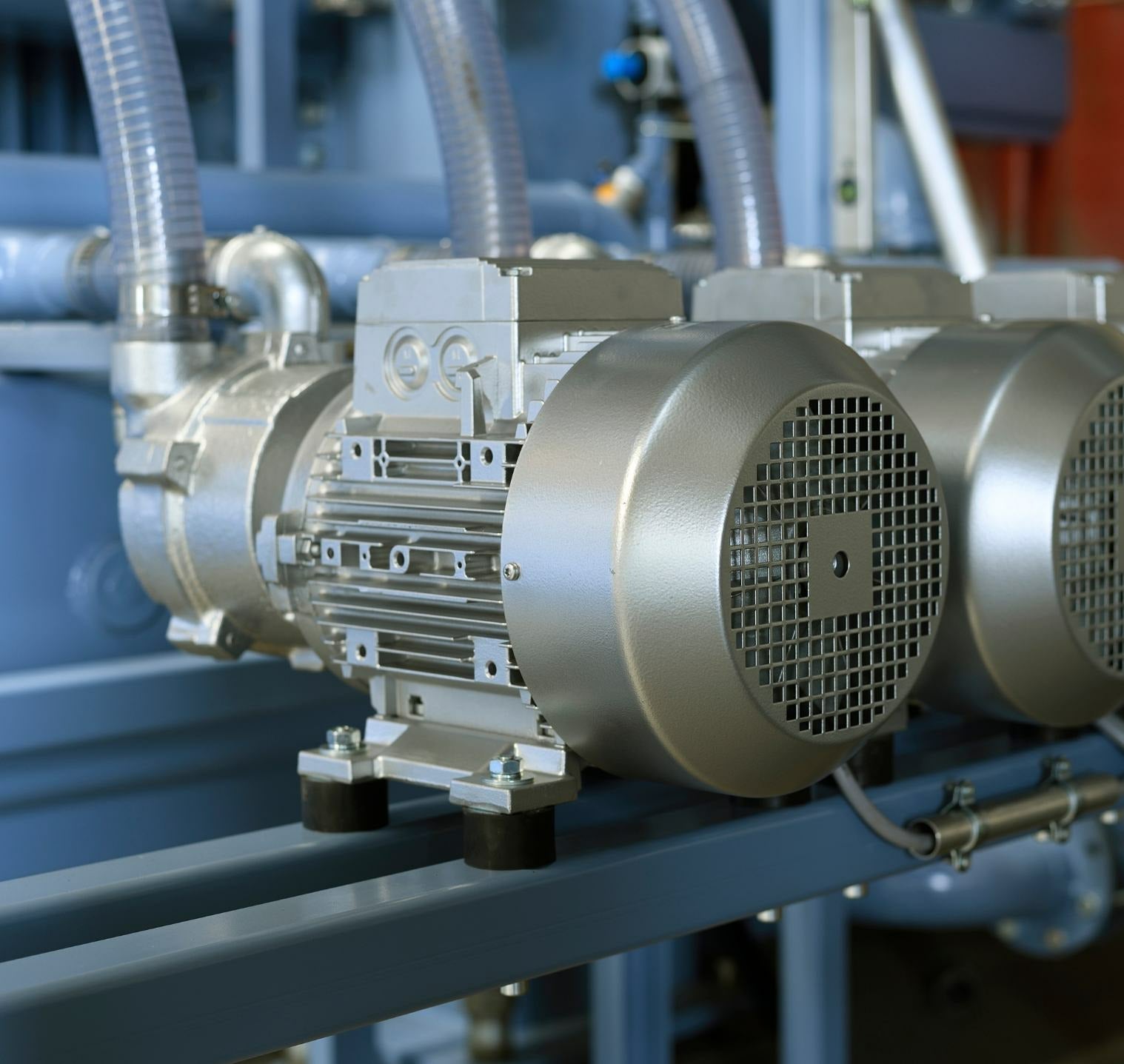
The single most important sizing decision is matching the fitting size to the pump inlet. Connecting a KF40 pump inlet with a KF25 fitting halves the cross-sectional flow area and dramatically reduces conductance — effective pump speed at the chamber can drop by 60% or more. Always match the fitting to the largest inlet port in the connection.
Conductance Calculation Primer
For viscous flow (rough vacuum), conductance scales roughly with the fourth power of tube diameter. In molecular flow (HV), it scales with the cube of diameter. Practically: a KF40 line has roughly 2.5× the conductance of an equivalent KF25 run. When pump-down time or base pressure matters, size up rather than down on main pump lines.
|
SIZING RULE Match fitting size to the largest port on any component in the run. If your turbomolecular pump has a KF40 inlet, use KF40 throughout the pump-to-chamber section. Reducers should only be used where unavoidable, and as close to the smaller-ported component as possible — not mid-run. |
3. Clamp Types — Standard Wing Clamps vs. Swing Clamps
KF flanges are held together by clamps. There are two main types used in laboratory vacuum, each with distinct advantages:
Standard Wing Clamps (Hinged Clamps)
The classic KF clamp is a two-piece hinged assembly with a central hinge and two wing handles that tighten against the outside of both flanges simultaneously. They are inexpensive, universally available, and reliable — the go-to for permanent or semi-permanent connections.
|
✓ Wing Clamp — Advantages ✓ Low cost — most economical option ✓ Universal — fits any matching KF size ✓ Proven and widely stocked ✓ Good for permanent / fixed connections ✓ Aluminium and stainless steel options |
✗ Wing Clamp — Limitations ✗ Requires two hands to assemble/remove ✗ Hinge can be awkward in tight spaces ✗ Less convenient for frequent-open ports ✗ Must be fully removed to open connection |
Swing Clamps (Single-Pivot Clamps)
Swing clamps attach permanently to one flange via a threaded bolt on one side. The opposing jaw swings open 180° to allow the second flange to be placed or removed, then swings shut and is tightened with a single nut or lever. They are significantly faster to operate with one hand, which makes them the preferred choice on any frequently-opened port — viewports, sample introduction, valve service, or gauge ports.
|
✓ Swing Clamp — Advantages ✓ One-handed operation — much faster ✓ Clamp stays attached — never lost ✓ Ideal for high-cycle-frequency ports ✓ Reduces assembly errors and fatigue ✓ Lever-lock versions: tool-free tightening |
✗ Swing Clamp — Limitations ✗ Higher cost than standard wing clamps ✗ Bolt must be matched to the flange ✗ Pivot pin requires occasional inspection ✗ Slightly bulkier in one axis |
|
WHEN TO USE SWING CLAMPS If a port is opened more than 2–3 times per week — sample loading, filter changes, valve maintenance — specify swing clamps from the outset. The productivity gain over a year of use far outweighs the price premium. For vacuum viewports and load-lock ports especially, swing clamps are almost always the right choice. |
4. Centring Rings & Seals — Material Selection
The centring ring sits between two mating KF flanges and locates the O-ring concentrically so it seals correctly. Centring rings are typically made from aluminium or stainless steel; the O-ring material determines the chemical and temperature compatibility of the seal.
|
Material |
Code |
Temp Range |
Best For |
Avoid With |
|
Viton (FKM) |
FPM |
−20 to +200°C |
Most lab apps, solvents, oils — standard choice |
Ketones, amines, low-MW esters |
|
Buna-N (NBR) |
NBR |
−40 to +120°C |
Budget option, hydrocarbon exposure |
Ozone, aromatic solvents, high temperature |
|
Silicone (VMQ) |
MVQ |
−60 to +200°C |
Cryogenic, food-grade, ozone resistance |
Poor oil/fuel resistance; higher permeability |
|
FFKM (Kalrez/Perlast) |
FFKM |
−10 to +327°C |
Aggressive chemicals, plasma, semiconductor |
Cost-prohibitive for general use |
|
PTFE (encapsulated) |
PTFE |
−70 to +230°C |
Highly corrosive media, HF, strong acids |
Poor elastic recovery — single use only |
|
⚠ CRITICAL — DO NOT REUSE DAMAGED O-RINGS An O-ring that shows flat-spotting (compression set), surface cracking, swelling, or tackiness must be replaced. Running a vacuum system on a compromised seal causes gradual leak-up that's difficult to diagnose and may be misattributed to pump failure or outgassing. Keep replacement O-rings stocked for every KF size in your system. |
5. How to Assemble a KF Connection Correctly
Step 1: Inspect Both Flange Faces
Check for scratches, dents, or contamination on the sealing face. Even minor radial scratches across the sealing groove can cause a slow leak. Clean with isopropanol and a lint-free wipe if necessary.
Step 2: Inspect and Lightly Grease the O-ring
Check the O-ring for damage. Apply a very thin smear of vacuum grease (Apiezon, Dow Corning, or equivalent) to lubricate — this aids installation and reduces the torque needed to seat the clamp. Do not over-grease; excess grease attracts particles and can contaminate the process.
Step 3: Place the Centring Ring and O-ring
The O-ring seats in the groove of the centring ring. Ensure it is not twisted or kinked. The centring ring sits in the bore of one flange face, recessed slightly so the other flange can mate squarely.
Step 4: Align and Mate the Flanges
Hold the flanges face-to-face and square — do not allow them to cock at an angle. If using a flexible bellows section, ensure it is not under lateral strain at the flange joint.
Step 5: Apply the Clamp and Tighten Evenly
For wing clamps, close the two halves over both flanges simultaneously and hand-tighten. You should feel the O-ring compress with a slight increase in resistance — do not over-torque. For swing clamps, swing the jaw closed and tighten finger-tight, then a quarter-turn further.
Step 6: Verify After Initial Pump-Down
On first pump-down with any new fitting assembly, monitor the pressure behaviour carefully. A slow leak at a KF joint typically shows as a system that pumps to an intermediate pressure and then stabilises. Use a helium leak detector or isopropanol wipe test to confirm.
6. Common Mistakes — and How to Avoid Them
⚠ Mixing KF sizes without a rated adaptor
KF25 and KF40 flanges are not compatible without a purpose-made KF25→KF40 reducing adaptor. Forcing mismatched sizes together with oversized clamps is a common workaround that compromises the seal, stresses the flange faces, and creates a leak point. Always use the correct reducing nipple or adaptor.
⚠ Over-tightening the clamp
More clamping force does not mean a better seal. Over-tightening extrudes the O-ring beyond the centring ring, cuts the O-ring on the flange edge, or distorts the centring ring. The correct torque is "firm hand-tight" — the O-ring should be compressed but not extruded. If you can see O-ring material squeezed out beyond the centring ring, it has been over-tightened.
⚠ Using the wrong O-ring material for the process
Buna-N O-rings installed in a system running acetone, MEK, or other ketones will swell and fail — sometimes rapidly. Always cross-reference the chemical resistance data for your specific elastomer against the gases and vapours present in your process, including cleaning solvents used for chamber maintenance.
⚠ Using KF fittings in UHV applications
KF O-ring seals have a permeation rate that limits ultimate pressure to approximately 10⁻⁷ Pa under ideal conditions. For UHV work below this level, ConFlat (CF) metal-seal flanges are required. The inherent permeability of any elastomer is the fundamental limitation, regardless of O-ring grade.
⚠ Ignoring flange orientation on angle fittings
KF elbows and tee pieces have a defined flow direction. Installing them backwards — particularly angle valves — can restrict flow or direct pump oil back towards the chamber. Check the flow arrow on valve bodies and ensure active components are oriented correctly.
⚠ Storing O-rings incorrectly
O-rings stored near UV sources, ozone-generating equipment, or in warm, humid conditions degrade significantly faster. Store in sealed bags in a cool, dark location. Discard any O-ring that has been stored loose and shows surface tackiness or haze.
⚠ Not stocking spare centring rings and O-rings
The most avoidable cause of system downtime is not having a replacement O-ring or centring ring when one fails during maintenance. Maintain a minimum of 5 spare sets per size in your lab consumables. Ezzi Vision supplies all standard KF sizes for next-business-day delivery across Australia.
7. Quick Reference — KF Fitting Selection Summary
|
Decision |
Recommended Choice |
Avoid |
|
Bore size for main pump line |
Match to largest pump port — KF40 or KF50 for most rotary pumps; KF40 for most turbos |
Under-sizing the main line to save cost |
|
Bore size for gauge/vent ports |
KF16 or KF25 — match to gauge head specification |
Over-sizing gauge ports (wastes space) |
|
Clamp — fixed connections |
Standard wing clamp (aluminium or stainless) |
Improvised fixing methods |
|
Clamp — high-cycle ports |
Swing clamp (lever-lock preferred) |
Wing clamps on ports opened daily |
|
O-ring material (default) |
Viton (FKM) |
Buna-N in solvent-rich environments |
|
O-ring (aggressive chemistry) |
FFKM (Kalrez/Perlast equivalent) |
Silicone where oil/fuel exposure possible |
|
Vacuum limit for KF fittings |
High vacuum ≥ 10⁻⁷ Pa |
UHV applications — use CF (ConFlat) instead |
|
Vacuum grease |
Apiezon L, M, or N; Dow Corning DC976 |
General-purpose PTFE or silicone grease |