


Vacuum Systems Basics
Vacuum technology underpins some of the most demanding work in science and industry — from semiconductor fabrication and thin-film coating to pharmaceutical freeze-drying and synchrotron research. Yet for many lab managers and procurement teams, the four core subsystems — pumps, gauges, chambers, and fittings — can feel like separate puzzles. This guide joins them into a single, coherent picture.
1. Vacuum 101 — Pressure Ranges That Matter
The word "vacuum" covers an enormous span of pressures. The atmosphere exerts about 101,325 Pa (760 Torr) at sea level. Scientific and industrial processes operate anywhere from a few hundred Pa down to 10⁻¹⁰ Pa — each decade of pressure reduction unlocking new capabilities and demanding new equipment.
|
Regime |
Pressure Range (Pa) |
Torr Equivalent |
Typical Applications |
|
Rough / Low Vacuum |
101,325 → 100 |
760 → ~1 |
Freeze-drying, vacuum ovens, packaging |
|
Medium Vacuum |
100 → 0.1 |
~1 → 10⁻³ |
Vacuum furnaces, degassing, impregnation |
|
High Vacuum (HV) |
0.1 → 10⁻⁴ |
10⁻³ → 10⁻⁶ |
Thin-film deposition, e-beam, mass spec |
|
Ultra-High Vacuum (UHV) |
< 10⁻⁴ |
< 10⁻⁶ |
Synchrotrons, surface science, LEED/RHEED |
|
KEY INSIGHT FOR PROCUREMENT Specifying equipment by pressure regime first — not brand — ensures every component in the chain is rated for the same duty. A roughing pump rated to 0.5 Pa paired with UHV fittings creates a well-matched system. Mixing pump capability with low-grade fittings is a common and expensive mistake. |
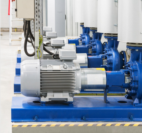
2. Vacuum Pumps — Creating the Pressure Differential
Pumps are the engine of any vacuum system. No single pump spans from atmosphere to UHV, which is why most high-vacuum systems use a two-stage pumping strategy: a roughing pump takes the system from atmosphere down to the operating pressure of a high-vacuum pump, which then drives pressure into the HV or UHV regime.
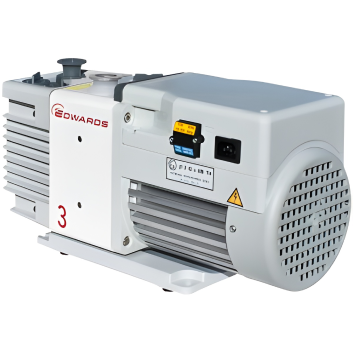
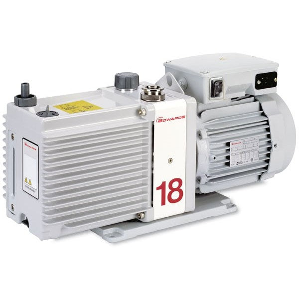
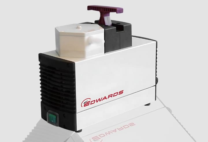
Rotary Vane Pumps
Oil-sealed, robust, and proven. Suitable for rough and medium vacuum down to ~0.1 Pa. Widely used as backing pumps. Require regular oil changes and exhaust mist filters. Edwards and Pfeiffer ranges are well established.
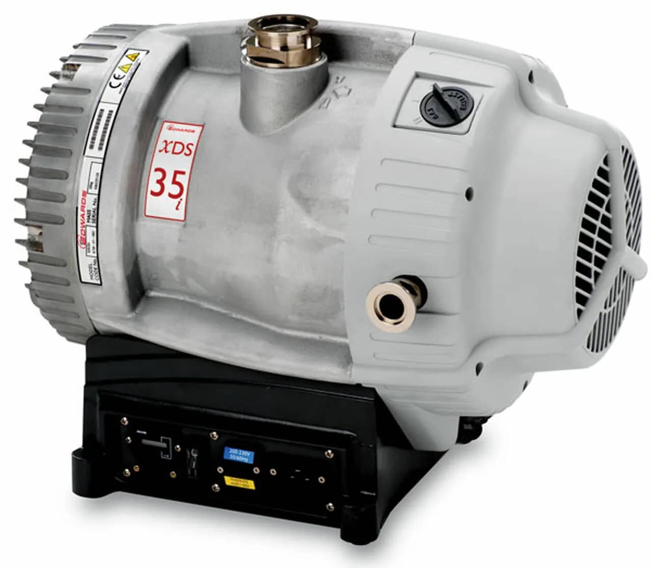
Dry Scroll Pumps
Oil-free design eliminates contamination risk — ideal for pharmaceutical, semiconductor, and clean-room environments. The Edwards XDS and nXDS series are popular examples. Ultimate pressure around 1–5 Pa.
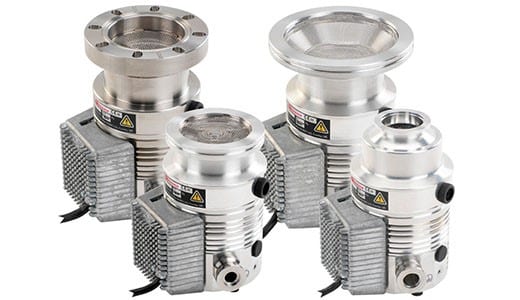
Turbomolecular Pumps
Rapidly spinning bladed rotors impart momentum to gas molecules, enabling high vacuum down to 10⁻⁸ Pa or better. Always require a backing (roughing) pump. Clean, fast, and controllable.
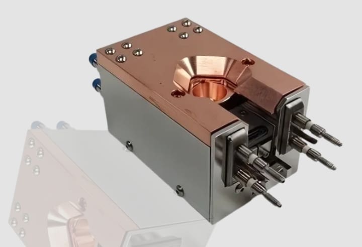
Cryogenic Pumps
Trap gas molecules on surfaces cooled to 10–20 K. No moving parts in the vacuum space means extremely clean pumping — particularly suited to large chambers and UHV systems.
|
BACKING PUMP MATCHING — RULE OF THUMB The inlet pressure of your high-vacuum pump must never exceed its rated maximum backing pressure. For most turbos, this is 0.5–5 Pa. Ensure the roughing pump can achieve this level before switching the turbo on. |
3. Vacuum Chambers — The Process Environment
The chamber defines the working volume of the system. Material choice, geometry, and surface finish all influence how quickly the chamber can be pumped down and what ultimate pressure is achievable.
Materials
Stainless steel (304 or 316L) is the industry standard for most HV and UHV chambers, offering low outgassing, good machinability, and compatibility with common cleaning protocols. Aluminium chambers are lighter and cheaper, well-suited to rough and medium vacuum. Glass and quartz chambers are used where optical access is critical.
Outgassing
Every surface inside a vacuum chamber releases adsorbed gases — water vapour being the dominant species in most labs. This outgassing rate is the primary limiting factor for achieving and holding base pressure. Baking a stainless steel chamber at 150–250°C for 12–48 hours can reduce outgassing by two to three orders of magnitude, a critical step in UHV preparation.
Ports and Access
Chambers ship with standardised flanged ports — KF (NW), ISO, or CF (ConFlat) — matched to the vacuum regime. Well-designed chambers provide dedicated ports for the pump connection, gauge head, process gases, electrical feedthroughs, and viewport access. Planning port layout at specification stage avoids costly machining later.
|
EZZI VISION TIP Ezzi Vision stocks and can custom-configure vacuum chambers with CF, KF, and ISO port combinations. Contact our team with your internal volume, port count, and target base pressure for a specification consultation. |
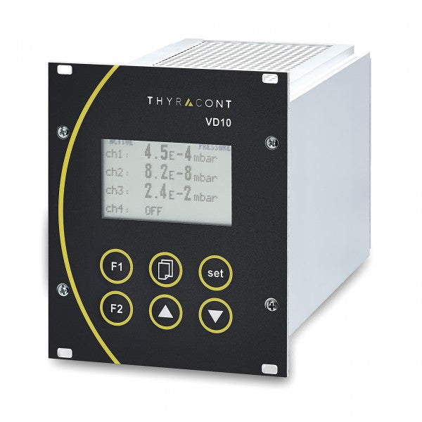
4. Vacuum Gauges — Knowing Where You Are
A vacuum system without gauging is blind. Gauges serve two distinct roles: confirming the system is performing as expected during normal operation, and diagnosing leaks or pump faults when it is not. Different measurement principles cover different pressure ranges, so most systems use at least two gauge types.
|
Gauge Type |
Operating Range |
Principle |
Notes |
|
Bourdon / Capacitance Manometer |
Atmosphere → ~1 Pa |
Mechanical / diaphragm deflection |
Gas-species independent; calibration stable |
|
Pirani Gauge |
10⁵ → ~0.1 Pa |
Thermal conductivity |
Low cost, fast response; reading varies with gas composition |
|
Penning (Cold Cathode) |
0.1 → 10⁻⁶ Pa |
Ionisation; magnetic field |
Robust, no filament; can misread at very low pressures |
|
Hot Cathode (Bayard-Alpert) |
10⁻² → 10⁻¹⁰ Pa |
Electron bombardment ionisation |
Accurate in HV/UHV; filament is consumable |
|
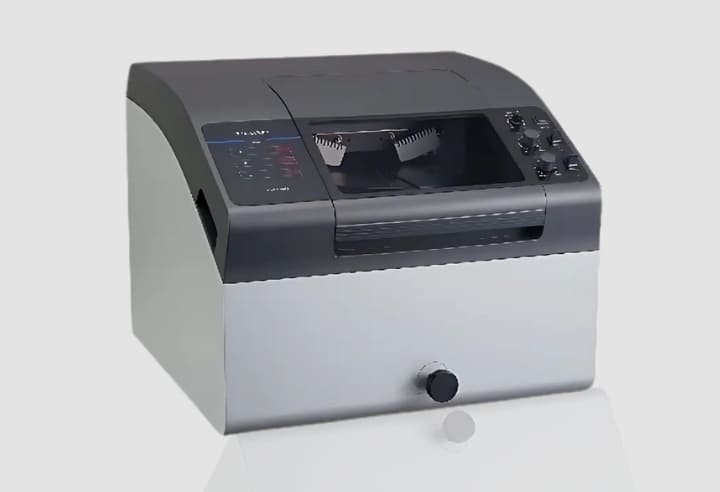
RGA (Residual Gas Analyser) |
10⁻³ → 10⁻¹⁰ Pa |
Quadrupole mass spectrometry |
Identifies species, not just pressure; leak detection |
Gauge Placement Matters
Place the gauge as close to the chamber as practically possible, and away from direct pump flow paths. Pressure readings near the pump inlet can be significantly lower than true chamber pressure due to gas flow dynamics — this leads to premature switching of high-vacuum pumps and potential damage.
5. Vacuum Fittings — Connecting It All
Fittings are the joints between every other component in the system. A single compromised fitting can prevent an entire system from reaching its design vacuum. There are three dominant fitting standards, each suited to a pressure regime:
|
Standard |
Also Known As |
Vacuum Range |
Seal Type |
Typical Use |
|
KF (NW) |
ISO-KF, Klein Flange |
Rough → High Vac (≥10⁻⁷ Pa) |
O-ring + centring ring |
Labs, R&D, backing lines |
|
ISO-F / ISO-K |
Large flange ISO |
Rough → High Vac |
O-ring in groove (ISO-F) / centring ring (ISO-K) |
Larger ports, industrial pumps |
|
CF (ConFlat) |
UHV flange |
Full UHV (<10⁻¹⁰ Pa) |
Copper or aluminium knife-edge gasket |
Synchrotrons, surface science, UHV systems |
|
⚠ CRITICAL WARNING Never mix KF and CF flanges on the same vacuum boundary without a purpose-made adaptor rated for the higher-vacuum side. CF flanges seal with a metal gasket crushed by bolts; KF flanges seal with an elastomer O-ring held by a clamp. The seal mechanisms are fundamentally different and not interchangeable. |
6. Valves — Controlling Gas Flow
Gate Valves
Provide an unobstructed, full-bore aperture when open — critical where pump-to-chamber conductance must be maximised. Used between the turbomolecular pump and chamber in HV/UHV systems. Available in manual, pneumatic, and electro-pneumatic actuation.
Angle Valves
Quarter-turn valves where the flow path changes direction through the valve body. Common on KF-fitted systems, they take less axial space than inline valves and are well-suited to rough-vacuum and backing lines.
Butterfly / Throttle Valves
Used for process pressure control — partially closing the valve between pump and chamber increases effective chamber pressure, useful in deposition processes where a controlled gas pressure is required.
Vent Valves
Allow controlled admission of dry nitrogen (or clean air) when bringing a system up to atmosphere. Venting too fast with ambient air risks contaminating the chamber with water vapour, dramatically extending the next pump-down time.
7. Putting It Together — System Design Principles
Conductance
Conductance describes how easily gas flows through a tube or fitting. Long, narrow tubes have low conductance and choke gas flow, slowing pump-down times. For HV and UHV systems, keep connections between the high-vacuum pump and chamber as short and wide as practical. This is why turbomolecular pumps are often mounted directly on the chamber.
Leak Rate vs. Throughput
The ultimate pressure a system achieves is the point where the pump throughput equals the total inflow — outgassing, permeation through seals, and any real leaks. Addressing leak rate (through proper fitting assembly, material selection, and baking) is often more impactful than upgrading to a larger pump.
Standard HV Startup Sequence
A standard startup sequence for an HV system with a roughing pump and turbomolecular pump:
– 1. Check all valves closed and all connections secure.
– 2. Start roughing pump; open rough valve to chamber; monitor Pirani gauge.
– 3. When chamber reaches turbopump backing pressure (~5 Pa), close rough valve.
– 4. Open backing valve and start turbomolecular pump.
– 5. Once turbo reaches full speed, open gate valve to chamber.
– 6. Monitor Penning or hot-cathode gauge for HV regime pressure.
FAQ — For Lab & Procurement Teams
Common questions from research labs, technical buyers, and facility managers across Australia and New Zealand.
Q: What vacuum level do I actually need for my application?
Start with the process requirement, not the equipment catalogue. Thin-film PVD typically needs 10⁻⁴ to 10⁻⁶ Pa; most pharmaceutical freeze-drying needs only 10–50 Pa; surface science may require 10⁻⁸ Pa or better. Over-specifying the vacuum level significantly increases cost and complexity without process benefit. Contact the Ezzi Vision technical team to discuss your specific application.
Q: Can I add a turbomolecular pump to my existing roughing pump system?
Possibly — but it depends on whether the roughing pump can achieve the required backing pressure for the turbo (typically below 5 Pa), and whether your existing fittings are rated for HV. KF fittings can handle HV if the O-rings are in good condition and properly cleaned, but all connections between the turbo and chamber must be HV-compatible. A system audit before purchasing is advisable.
Q: How do I know if I have a real leak or just outgassing?
Both cause poor ultimate pressure, but they respond differently to time and temperature. Outgassing decreases over time as residual gas is pumped away (and much faster with baking). A real leak maintains a steady inflow regardless of pumping time. The definitive diagnostic tool is a Residual Gas Analyser (RGA) — a peak at mass 18 (water) that declines over hours suggests outgassing; a persistent nitrogen/oxygen signature at mass 28/32 indicates an atmospheric leak.
Q: What's the difference between oil-sealed and dry (oil-free) roughing pumps?
Oil-sealed rotary vane pumps offer lower ultimate pressure and higher throughput per dollar, but require regular oil changes and produce oil mist in the exhaust (requiring mist filters). Dry scroll pumps like the Edwards XDS series are more expensive upfront but eliminate contamination risk, require less maintenance, and are preferable wherever process cleanliness matters — pharmaceutical, semiconductor, food science. In cleanroom environments, dry pumps are essentially mandatory.
Q: How often should O-rings and seals be replaced?
This depends on elastomer type, operating temperature, and how frequently the system is cycled between vacuum and atmosphere. As a general rule, visually inspect O-rings every time a fitting is opened, and replace any that show compression set (a flat profile), cracking, or stickiness. Viton (FKM) O-rings are the standard for most vacuum applications; FFKM (Kalrez/Perlast) should be used where chemical compatibility is a concern. Keep a stock of spares for your most-used fitting sizes — KF25 and KF40 are the most commonly needed.
Q: Our system isn't reaching its rated base pressure. Where do we start troubleshooting?
Work systematically from the pump outward. First, verify pump performance by blanking off the inlet and measuring ultimate pressure. Then check all fitting joints for leaks using helium spray or isopropanol swab. Check O-ring condition and that all clamps are properly tightened. Finally, consider chamber outgassing — a period of baking with the pump running can reveal whether surface contamination is limiting performance.
Q: What gauge do we need for a system targeting 10⁻⁶ Pa?
You need at least two gauges. A Pirani gauge covers the roughing phase from atmosphere to about 0.1 Pa and is used to confirm backing pressure before starting the high-vacuum pump. A Penning (cold cathode) or Bayard-Alpert (hot cathode) ionisation gauge covers the HV range from ~0.1 Pa to below 10⁻⁶ Pa. Many modern gauge controllers combine both measurement principles in a single unit with automatic range-switching, which simplifies wiring and readout.
Q: Can Ezzi Vision supply a complete, pre-tested vacuum system?
Yes — we regularly configure and supply complete vacuum systems for research and industrial customers across Australia and New Zealand. This includes system design, component sourcing from our 18+ brand partnerships, assembly, leak testing, and commissioning support. Contact our team at sales@ezzivision.com.au or call 1-800-463994 to discuss your requirements.